|
 10-05-2009, 12:06 AM
|
#1
|
|
Power Member/NJFBOA Bookie/Moderator
Join Date: Jun 2009
Location: North Jersey = Best Jersey.
Posts: 4,435
|
Wiring DPDT & Cutout.
Answer in post 14: http://www.njfboa.org/forums/showpos...2&postcount=14
How do I wire this all up to the 6 prongs on the back of the switch?
- There are 4 wires coming off of the cutout--Red, White, Green, Black.
- From messing around with the wires, I've learned that Red to Negative & Green to Positive will OPEN the cutout.
- Red to Positive & Green to Negative will CLOSE the cutout.
- I don't know what the black or white wires do.
It's going in the ashtray, by the cigarette lighter.
 
Last edited by Jersey Mike; 10-10-2009 at 06:10 PM.
|

|

|
|
10-05-2009, 12:13 AM
|
#2
|
Join Date: May 2009
Location: Detpford New Jersey
Posts: 204
|
Hmm heres a guess.
Black Power
White Neutral
Red Common
Green Ground.
|
|
|
|
|
10-05-2009, 12:16 AM
|
#3
|
|
Power Member/NJFBOA Bookie/Moderator
Join Date: Jun 2009
Location: North Jersey = Best Jersey.
Posts: 4,435
|
I need a little more specific help--you can't underestimate my inexperience when it comes to Electrical.
I'm looking for specific colors to specific prongs -- ie: "Red to Top Left"
|
|
|
|
|
10-05-2009, 12:26 AM
|
#4
|
Join Date: May 2009
Location: Detpford New Jersey
Posts: 204
|
Here try this.
Black is your top left. White is your top right.
Red Middle Left . Green middle right.
Than you jump top left to bottom right
Then you jump top right to bottom left.
Last edited by Czop418; 10-05-2009 at 12:43 AM.
|
|
|
|
|
10-05-2009, 12:57 AM
|
#5
|
|
Power Member/NJFBOA Bookie/Moderator
Join Date: Jun 2009
Location: North Jersey = Best Jersey.
Posts: 4,435
|
Quote:
Originally Posted by Czop418

Here try this.
Black is your top left . White is your top right.
Red Middle Left . Green middle right.
Than you jump top left to bottom right . Then you jump top right to bottom left.
|
so I dont need to splice into the cig lighter or run a ground to a screw or anything?
|
|
|
|
|
10-05-2009, 01:05 AM
|
#6
|
|
Power Member/NJFBOA Bookie/Moderator
Join Date: Jun 2009
Location: North Jersey = Best Jersey.
Posts: 4,435
|
Here's what I had thought:
*Green ______________________ *Red
*Run a wire from the Cig lighter __*Run a wire to a ground
*Red ________________________*Green
Leaving the Black & White wires out of the equation(since the cutout opened & closed without them..)
but, I'm not sure how that'd work
Last edited by Jersey Mike; 10-05-2009 at 01:10 AM.
|
|
|
|
|
10-05-2009, 01:20 AM
|
#7
|
Join Date: May 2009
Location: Detpford New Jersey
Posts: 204
|
Oh damn sorry what i told you is wrong damn im tired. Let Me think about this for a moment.
Middle Left Is you + Middle Right is your - Which is from your cigarette lighter
Than hook your Red to top left
Than Green to top right.
Than just jump them.
Red to bottom left
And green to bottom right. The other 2 wires are not needed its only if you were gonna use a different switch.
|
|
|
|
|
10-05-2009, 01:21 AM
|
#8
|
Join Date: May 2009
Location: Detpford New Jersey
Posts: 204
|
Quote:
Originally Posted by Jersey Mike
Here's what I had thought:
*Green ______________________ *Red
*Run a wire from the Cig lighter __*Run a wire to a ground
*Red ________________________*Green
Leaving the Black & White wires out of the equation(since the cutout opened & closed without them..)
but, I'm not sure how that'd work
|
Thats exactly right. The point of a DPDT is to reverse the polarity.
Last edited by Czop418; 10-05-2009 at 01:27 AM.
|
|
|
|
|
10-05-2009, 10:03 AM
|
#9
|
|
Power Member/NJFBOA Bookie/Moderator
Join Date: Jun 2009
Location: North Jersey = Best Jersey.
Posts: 4,435
|
^^ Alright, I'm going to go try it now & hopefully that works.
|
|
|
|
|
10-05-2009, 11:34 AM
|
#10
|
Join Date: Dec 2008
Location: NNJ
Posts: 1,489
|
Quote:
Originally Posted by Jersey Mike
^^ Alright, I'm going to go try it now & hopefully that works.
|
lmk i could probably get a pic of mine
__________________
1997 Camaro Z28 - 355 LT1, T56, CC503, LTs, ORY, Bald Eagle-back exhaust, !emissions, Lingenfelter CAI, EWP, !CAGS, BMR LCAs, UMI PHB, Koni Str.t/Koni SA, C5 Z06 front / LS1 F-body rear brake swap, factory hurst with short stick  2014 2LT Cruze 2.0 Turbo Diesel
|
|
|
|
|
10-05-2009, 04:43 PM
|
#11
|
|
Power Member/NJFBOA Bookie/Moderator
Join Date: Jun 2009
Location: North Jersey = Best Jersey.
Posts: 4,435
|
Didn't work.
The ground wire is good & so is the + wire; I tested them with an LED strip & it lit them up just fine. So the problem is either:
A) There is some caulking on the switch & a tiny bit on the base of some prongs (needed to hold switch to ashtray, caulk was the only thing at my disposal at the time). It's only a tiny bit on the outside base of the prongs, but maybe that is not stopping the electricity from flowing?
B) The switch I bought from RadioShack could is bad?
C) There were 6 or so threads on each wire coming off the cutout. Two of them on one wire twisted off--since they're so delicate--while I was twisting them onto the holes in the switch. So, only 2 threads went to each prong for the Green wire. Could there have not been sufficient threads on those two prongs that caused it to not work?
D) None of the above. Just wired incorrectly?
|
|
|
|
|
10-05-2009, 10:18 PM
|
#12
|
|
Co-Founder / Site Admin
Join Date: Jul 2004
Location: Ewing, NJ
Posts: 22,476
|
Quote:
Originally Posted by Jersey Mike
C) There were 6 or so threads on each wire coming off the cutout. Two of them on one wire twisted off--since they're so delicate--while I was twisting them onto the holes in the switch. So, only 2 threads went to each prong for the Green wire. Could there have not been sufficient threads on those two prongs that caused it to not work?
|
This may not be the reason for it not to work, but it's far from the ideal setup.
Do you have extra wire? If so, cut a few inches off of the green and red wire lengths and use that to jump from corner to corner on the switch. then run the green and red wire left from the cutout to the corners of the switch as directed above.
Understand?
- Justin
__________________
1999 Camry - Beigemobile DD
2002 Suburban - Wife's DD
2004 Grand Cherokee - Not running / Project / Selling?

|
|
|
|
|
10-05-2009, 10:59 PM
|
#13
|
|
Power Member/NJFBOA Bookie/Moderator
Join Date: Jun 2009
Location: North Jersey = Best Jersey.
Posts: 4,435
|
Quote:
Originally Posted by Tru2Chevy
This may not be the reason for it not to work, but it's far from the ideal setup.
Do you have extra wire? If so, cut a few inches off of the green and red wire lengths and use that to jump from corner to corner on the switch. then run the green and red wire left from the cutout to the corners of the switch as directed above.
Understand?
- Justin
|
Ya, it's going to be tight because there's not much wire to work with, but she can probably spare a few inches.
To make sure I'm understanding this correctly, connect the criss-cross, then run the wire from the cutout to only one prong each, or to all four corners?
|
|
|
|
|
10-05-2009, 11:13 PM
|
#14
|
Join Date: May 2009
Location: Detpford New Jersey
Posts: 204
|
well you should go out and buy the right connectors for the wires it should look like this.
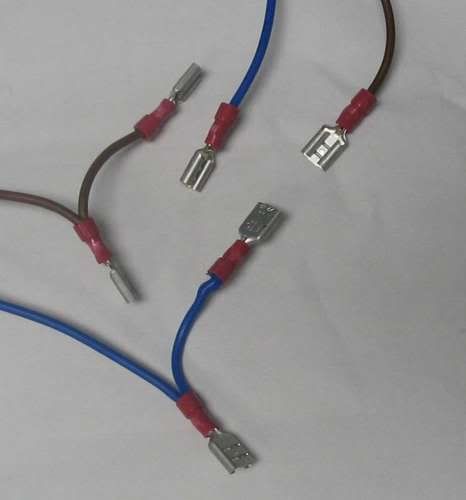
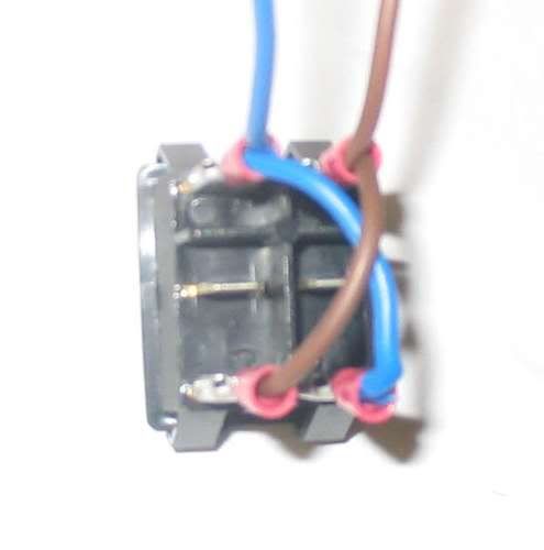
Then your final product should look like this
Last edited by Czop418; 10-05-2009 at 11:14 PM.
|
|
|
|
|
10-05-2009, 11:16 PM
|
#15
|
|
Co-Founder / Site Admin
Join Date: Jul 2004
Location: Ewing, NJ
Posts: 22,476
|
Quote:
Originally Posted by Czop418
|
This is definitely the right way of doing it....
- Justin
__________________
1999 Camry - Beigemobile DD
2002 Suburban - Wife's DD
2004 Grand Cherokee - Not running / Project / Selling?
|
|
|
|
|
10-05-2009, 11:20 PM
|
#16
|
|
Power Member/NJFBOA Bookie/Moderator
Join Date: Jun 2009
Location: North Jersey = Best Jersey.
Posts: 4,435
|
Wow, that looks so clean, so easy.
what are those connectors called, and do they simply slide over the prongs snuggly?
The pictures are very helpful.
|
|
|
|
|
10-05-2009, 11:23 PM
|
#17
|
Join Date: May 2009
Location: Detpford New Jersey
Posts: 204
|
Alot of people call em different things. Thats why i showed you what they look like. I call them Female Spades. Some people call them Female Terminals.
|
|
|
|
|
10-05-2009, 11:23 PM
|
#18
|
|
Meet Coordinator
Join Date: Jan 2008
Location: brick/pt. pleasant beach
Posts: 19,371
|
spaded connectors, yes, you need to "crimp" them onto the wire though. google it up
|
|
|
|
|
10-05-2009, 11:26 PM
|
#19
|
Join Date: May 2009
Location: Detpford New Jersey
Posts: 204
|
Here ya go this might help you out step by step pictures on how too.
http://www.instructables.com/id/HOW-...-reversing-po/
Oh and by the way i would cut up wires and make your own harness. That way incase you do mess anything up your not messing with the cut out wires. And when your done just wire nut them together or get butt-end connectors.
Last edited by Czop418; 10-05-2009 at 11:30 PM.
|
|
|
|
|
10-05-2009, 11:30 PM
|
#20
|
|
Power Member/NJFBOA Bookie/Moderator
Join Date: Jun 2009
Location: North Jersey = Best Jersey.
Posts: 4,435
|
awesome. thanks.
|
|
|
|
|
10-08-2009, 10:09 AM
|
#21
|
|
Banned
Join Date: Dec 2007
Posts: 1,106
|
did you get it to work?
|
|
|
|
|
10-08-2009, 07:45 PM
|
#22
|
|
Power Member/NJFBOA Bookie/Moderator
Join Date: Jun 2009
Location: North Jersey = Best Jersey.
Posts: 4,435
|
Haven't tried. Enjoying the "open" position too much  Going back home tomorrow, so I will buying the spade connectors & trying again then.
|
|
|
|
|
10-08-2009, 07:49 PM
|
#23
|
|
Banned
Join Date: Dec 2007
Posts: 1,106
|
Quote:
Originally Posted by Jersey Mike
Haven't tried. Enjoying the "open" position too much Going back home tomorrow, so I will buying the spade connectors & trying again then. |
I tried the way they said to on my older switch and motor and it worked out fine.
|
|
|
|
|
10-10-2009, 06:09 PM
|
#24
|
|
Power Member/NJFBOA Bookie/Moderator
Join Date: Jun 2009
Location: North Jersey = Best Jersey.
Posts: 4,435
|
Thanks Czop. I did it using spade connectors & added an extra (cross) wire like the pictures show and it now works.
I appreciate the help guys. Thanks.
Quote:
Originally Posted by Czop418
|
|
|
|
|
 Posting Rules
|
You may not post new threads
You may not post replies
You may not post attachments
You may not edit your posts
HTML code is Off
|
|
|
|
|
|